Datums must be of sufficient size - 1994, 2009, 2018 (#30)
(In accordance with the ASME Y14.5-2018 standard)
(In accordance with the ASME Y14.5-2009 standard)
(In accordance with Y14.5M-1994 standard)
PDF is Available with GD&T Reference Center Subscription.
When discussing parts like the one shown below, people often ask why datum A is referenced in the position callout. After all, the hole locating dimensions are from datums B and C. One reason to include datum A is to control the perpendicularity of the four holes. Since the part is so thin, it is unlikely that the holes would ever fail the positional requirement because they were tipped too much relative to datum A. A more important reason to include datum A as a datum reference is to assure a stable setup for inspection of the part. A planar primary datum takes away 3 degrees of freedom. Datum feature B is too narrow to reproducibly take away more than 2 degrees of freedom. It is not “sufficient in size to permit its use” (section 4.3 in 1994, 4.8 in 2009, and 7.8 in 2018), in this case as a primary datum feature. A major purpose for selecting the correct datum features is to assure reproducible inspection of parts. Datum feature A is sufficient in size (area) to accomplish this. Using datum features B or C as a primary datum would be like trying to balance a credit card on its’ edge.
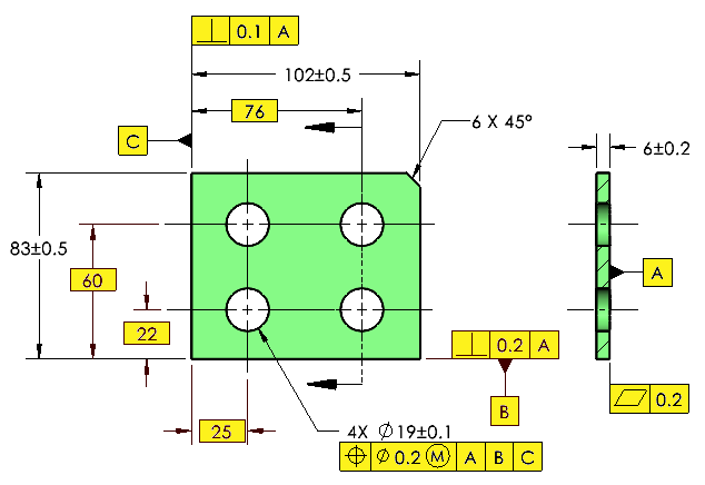
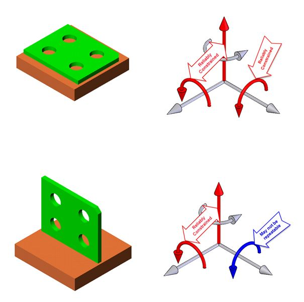
Fig 1: Datum feature A is a stable primary datum feature: All 3 degrees of freedom are reliably constrained.
Fig 2: Datum feature B may be an unstable primary datum feature: Rotation about the edge may not be repeatable.
This tip is in accordance with ASME Y14.5M-1994, Y14.5-2009 and Y14.5-2018.
This tip was originally released in December 1999.
